An
electric motor converts
electrical energy into
mechanical energy.
Most electric
motors operate through the interaction of
magnetic fields and
current-carrying conductors to generate force. The reverse process, producing electrical energy from mechanical energy, is done by
generators such as an
alternator or a
dynamo; some electric motors can also be used as generators, for example, a
traction motor on a vehicle may perform both tasks. Electric motors and generators are commonly referred to as
electric machines.
Electric motors are found in applications as diverse as industrial fans, blowers and
pumps, machine tools, household appliances,
power tools, and
disk drives. They may be powered by
direct current,
e.g., a
battery powered portable device or motor vehicle, or by
alternating current from a central
electrical distribution grid or
inverter. The smallest motors may be found in
electric wristwatches. Medium-size motors of highly standardized dimensions and characteristics provide convenient mechanical power for industrial uses. The very largest electric motors are used for propulsion of ships, pipeline compressors, and
water pumps with ratings in the millions of
watts. Electric motors may be classified by the source of electric power, by their internal construction, by their application, or by the type of motion they give.
The physical principle of production of mechanical force by the interactions of an electric current and a magnetic field was known as early as 1821. Electric motors of increasing efficiency were constructed throughout the 19th century, but commercial exploitation of electric motors on a large scale required efficient
electrical generators and
electrical distribution networks.
Some devices convert electricity into motion but do not generate usable mechanical power as a primary objective and so are not generally referred to as electric motors. For example,
magnetic solenoids and
loudspeakers are usually described as
actuators and
transducers,
[1] respectively, instead of motors. Some electric motors are used to produce torque or force.
[2]
History and development
Faraday's electromagnetic experiment, 1821
[3] 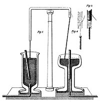
The conversion of electrical energy into mechanical energy by
electromagnetic means was demonstrated by the British scientist
Michael Faraday in 1821. A free-hanging wire was dipped into a pool of
mercury, on which a
permanent magnet was placed. When a
current was passed through the wire, the wire rotated around the magnet, showing that the current gave rise to a close circular magnetic field around the wire.
[4] This motor is often demonstrated in school physics classes, but
brine (salt water) is sometimes used in place of the toxic mercury. This is the simplest form of a class of devices called
homopolar motors. A later refinement is the
Barlow's wheel. These were demonstration devices only, unsuited to practical applications due to their primitive construction.
[citation needed]
historic motor still works perfectly today.
[5])
In 1827,
Hungarian physicist Ányos Jedlik started experimenting with devices he called "electromagnetic self-rotors". Although they were used only for instructional purposes, in 1828 Jedlik demonstrated the first device to contain the three main components of practical
direct current motors: the
stator,
rotor and
commutator. The device employed no permanent magnets, as the magnetic fields of both the stationary and revolving components were produced solely by the currents flowing through their windings.
[6][7][8][9][10][11]
[edit] The first electric motors
The first
commutator-type direct current electric motor capable of turning machinery was invented by the British scientist
William Sturgeon in 1832.
[12] Following Sturgeon's work, a commutator-type direct-current electric motor made with the intention of commercial use was built by Americans
Emily and
Thomas Davenport and patented in 1837. Their motors ran at up to 600 revolutions per minute, and powered machine tools and a printing press.
[13] Due to the high cost of the
zinc electrodes required by
primary battery power, the motors were commercially unsuccessful and the Davenports went bankrupt. Several inventors followed Sturgeon in the development of DC motors but all encountered the same cost issues with primary battery power. No electricity distribution had been developed at the time. Like Sturgeon's motor, there was no practical commercial market for these motors.
[citation needed]
In 1855 Jedlik built a device using similar principles to those used in his electromagnetic self-rotors that was capable of useful work.
[6][8] He built a model
electric motor-propelled vehicle that same year.
[14]
The modern DC motor was invented by accident in 1873, when
Zénobe Gramme connected the
dynamo he had invented to a second similar unit, driving it as a motor. The
Gramme machine was the first electric motor that was successful in the industry.
[citation needed]
In 1886
Frank Julian Sprague invented the first practical DC motor, a non-sparking motor capable of constant speed under variable loads. Other Sprague electric inventions about this time greatly improved grid electric distribution (prior work done while employed by
Thomas Edison), allowed power from electric motors to be returned to the electric grid, provided for electric distribution to trolleys via overhead wires and the trolley pole, and provided controls systems for electric operations. This allowed Sprague to use electric motors to invent the first electric trolley system in 1887–88 in Richmond VA, the electric elevator and control system in 1892, and the electric subway with independently powered centrally controlled cars, which was first installed in 1892 in Chicago by the South Side Elevated Railway where it became popularly known as the "L". Sprague's motor and related inventions led to an explosion of interest and use in electric motors for industry, while almost simultaneously another great inventor was developing its primary competitor, which would become much more widespread.
In 1888
Nikola Tesla invented the first practicable
AC motor and with it the
polyphase power transmission system. Tesla continued his work on the AC motor in the years to follow at the Westinghouse company.
The development of electric motors of acceptable efficiency was delayed for several decades by failure to recognize the extreme importance of a relatively small air gap between rotor and stator. Efficient designs have a comparatively small air gap.
[15]
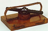
The St. Louis motor, long used in classrooms to illustrate motor principles, is extremely inefficient for the same reason, as well as appearing nothing like a modern motor. Photo of a traditional form of the St. Louis motor:
[4]
Application of electric motors revolutionized industry. Industrial processes were no longer limited by power transmission using line shafts, belts, compressed air or hydraulic pressure. Instead every machine could be equipped with its own electric motor, providing easy control at the point of use, and improving power transmission efficiency. Electric motors applied in agriculture eliminated human and animal muscle power from such tasks as handling grain or pumping water. Household uses of electric motors reduced heavy labor in the home and made higher standards of convenience, comfort and safety possible. Today, electric motors consume more than half of all electric energy produced.
[16][17]
Brushed DC motors
DC motors have AC in a wound rotor also called an
armature, with a split ring
commutator, and either a wound or permanent magnet stator. The commutator and brushes are a long-life rotary switch. The rotor consists of one or more coils of wire wound around a laminated "soft" ferromagnetic core on a shaft; an electrical power source feeds the rotor windings through the commutator and its brushes, temporarily magnetizing the rotor core in a specific direction. The commutator switches power to the coils as the rotor turns, keeping the magnetic poles of the rotor from ever fully aligning with the magnetic poles of the stator field, so that the rotor never stops (like a compass needle does), but rather keeps rotating as long as power is applied.

Many of the limitations of the classic
commutator DC motor are due to the need for brushes to press against the commutator. This creates
friction. Sparks are created by the brushes making and breaking circuits through the rotor coils as the brushes cross the insulating gaps between commutator sections. Depending on the commutator design, this may include the brushes shorting together adjacent sections – and hence coil ends – momentarily while crossing the gaps. Furthermore, the
inductance of the rotor coils causes the voltage across each to rise when its circuit is opened, increasing the sparking of the brushes. This sparking limits the maximum speed of the machine, as too-rapid sparking will overheat, erode, or even melt the commutator. The current density per unit area of the brushes, in combination with their
resistivity, limits the output of the motor. The making and breaking of electric contact also generates
electrical noise; sparking generates
RFI. Brushes eventually wear out and require replacement, and the commutator itself is subject to wear and maintenance (on larger motors) or replacement (on small motors). The commutator assembly on a large motor is a costly element, requiring precision assembly of many parts. On small motors, the commutator is usually permanently integrated into the rotor, so replacing it usually requires replacing the whole rotor.
While most commutators are cylindrical, some are flat discs consisting of several segments (typically, at least three) mounted on an insulator.
Large brushes are desired for a larger brush contact area to maximize motor output, but small brushes are desired for low mass to maximize the speed at which the motor can run without the brushes excessively bouncing and sparking (comparable to the problem of "
valve float" in internal combustion engines). (Small brushes are also desirable for lower cost.) Stiffer brush springs can also be used to make brushes of a given mass work at a higher speed, but at the cost of greater friction losses (lower efficiency) and accelerated brush and commutator wear. Therefore, DC motor brush design entails a trade-off between output power, speed, and efficiency/wear.
- Notes on terminology
- The first practical electric motors, used for street railways, were DC with commutators. Power was fed to the commutators (made of copper) by copper brushes, but the voltage difference between adjacent commutator bars, excellent conductivity of the copper brushes, and arcing created considerable damage after only a quite short period of operation. An electrical engineer realized that replacing the copper brushes with electrically resistive solid carbon blocks would provide much longer life. Although the term is no longer descriptive, the carbon blocks continue to be called "brushes" even to this day.
- Sculptors who work with clay need support structures called armatures to keep larger works from sagging due to gravity. Magnetic laminations, in a rotor with windings, similarly support insulated-copper-wire coils. By analogy, wound rotors came to be called "armatures".[citation needed]
- Commutators, at least among some people who work with them daily, have become so familiar that some fail to realize that they are just a particular variety of rotary electrical switch. Considering how frequently connections make and break, they have very long lifetimes.
A: shunt
B: series
C: compound
f = field coil
There are five types of brushed DC motor:
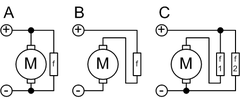
- DC shunt-wound motor
- DC series-wound motor
- DC compound motor (two configurations):
- Cumulative compound
- Differentially compounded
- Permanent magnet DC motor (not shown)
- Separately excited (not shown)
View the original article here
 The configuration of the 3-phase synchronous motor consists of a central stator which supports the windings and the inverter, surrounded by an external rotor which supports the permanent magnets. The motor assembly is liquid-cooled to sustain high continuous power demands.
  friction clutch - a clutch in which one part turns the other by the friction between them


![[4]](http://www.physics.umd.edu/lecdem/services/demos/demosk4/k4-21.gif)